- 您现在的位置:买卖IC网 > Sheet目录311 > AS5134 PB (ams)BOARD PROGRAM AS5134
�� �
�
�AS5134�
�Datasheet� -� D� e� t� a� i� l� e� d� D� e� s� c� r� i� p� t� i� o� n�
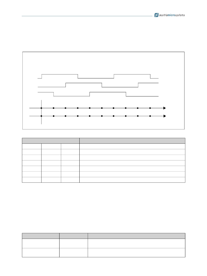
�7.9� Brushless� DC� Motor� Commutation� Mode�
�The� BLDC� signals� will� be� used� to� control� the� electrical� angle� information� –� according� to� the� amount� of� pole� pairs� and� the� actual� mechanical� angle�
�position.� Refer� Figure� 13� for� an� example� of� n_pole_pairs:=2.� For� the� programming,� refer� to� Serial� Synchronous� Interface� (SSI)� on� page� 18� .�
�Figure� 13.� Commutation� Mode�
�?� electrical� :=� ?� mechanical� *n� pole_pairs�
�pole� pair� :� 2�
�U�
�V�
�W�
�0�
�0�
�60�
�30�
�120�
�60�
�180�
�90�
�240�
�120�
�300�
�150�
�0�
�180�
�60�
�210�
�120�
�240�
�180�
�270�
�angle� electrical�
�angle� mechanical�
�Table� 8.� Programming� Options� for� the� Commutation� Signals� U/V/W�
�uvw� (11:9)�
�Function�
�0�
�0�
�0�
�0�
�1�
�1�
�1�
�0�
�0�
�1�
�1�
�0�
�0�
�1�
�0�
�1�
�0�
�1�
�0�
�1�
�1�
�BLDC� Pole� Pairs� :� 1� ?� electrical� angle� of� 60o� =� mechanical� angle:� 60o�
�BLDC� Pole� Pairs� :� 2� ?� electrical� angle� of� 60o� =� mechanical� angle:� 30o�
�BLDC� Pole� Pairs� :� 3� ?� electrical� angle� of� 60o� =� mechanical� angle:� 20o�
�BLDC� Pole� Pairs� :� 4� ?� electrical� angle� of� 60o� =� mechanical� angle:� 15o�
�BLDC� Pole� Pairs� :� 5� ?� electrical� angle� of� 60o� =� mechanical� angle:� 12o�
�BLDC� Pole� Pairs� :� 6� ?� electrical� angle� of� 60o� =� mechanical� angle:� 10o�
�off� ?� LO� pad� U,� V,� W,� PWM�
�7.10� Daisy� Chain� Mode�
�The� angle� information� from� the� device� and� the� setup� for� the� device� is� handled� over� the� digital� interface.� A� special� port� (Dx)� can� be� used� to�
�implement� a� daisy� chain� mode.� Depending� on� the� configuration,� it� is� possible� to� implement� a� two� wire� or� a� three� wire� mode.� In� the� three� wire�
�mode,� each� communication� starts� with� the� rising� edge� of� the� chip� select� signal.� The� Port� Dx� is� used� to� transfer� the� chip� select� information� from�
�one� device� to� the� next.� Refer� to� Figure� 14� and� Figure� 15� .� In� the� two� wire� interface� mode,� a� timeout� logic� ensures� that� the� digital� interface� will� be�
�reset� if� there� is� no� clock� source� available� for� a� certain� time.� The� synchronization� between� the� internal� free� running� analog� clock� oscillator� and� the�
�external� used� digital� clock� source� for� the� digital� interface� is� done� in� a� way� that� the� digital� clock� frequency� can� vary� in� a� wide� range.�
�Remark:� Reset� for� the� digital� interface:�
�3� wire� mode� ?� via� chip� select�
�2� wire� mode� ?� via� timeout�
�Port�
�Chip� Select�
�DCLK�
�Symbol�
�CS�
�DCLK�
�Function�
�Indicates� the� start� of� a� new� access� cycle� to� the� device�
�CS� =� LO� ?� reset� of� the� digital� interface.�
�Clock� source� for� the� communication� over� the� digital� interface.� The� maximum� and�
�minimum� frequency� depends� on� the� mode.�
�www.austriamicrosystems.com/AS5134�
�Revision� 2.3�
�15� -� 32�
�发布紧急采购,3分钟左右您将得到回复。
相关PDF资料
AS5140 PB
BOARD PROGRAM AS5140
ASDMB-ADAPTER-KIT
ASDMB MEMSPEED P II OSC KIT
ASFLMPLP-ADAPTER-KIT
ASFLMPLP MEMSPEED P II OSC KIT
AT24C01-10SI-1.8
IC EEPROM 1KBIT 400KHZ 8SOIC
AT24C01B-TSU-T
IC EEPROM 1KBIT 1MHZ SOT23-5
AT24C02C-XHM-B
IC EEPROM 2KBIT 1MHZ 8TSSOP
AT24C04AN-10SI-2.7
IC EEPROM 4KBIT 400KHZ 8SOIC
AT24C08B-PU
IC EEPROM 8KBIT 1MHZ 8DIP
相关代理商/技术参数
AS5134-AB
制造商:ams 功能描述:AS5134 Adapter Board
AS5134-ASSU
制造商:AMS 功能描述:ENCODER MAGNETIC ROTARY 8BIT 20SSOP 制造商:AMS 功能描述:ENCODER, MAGNETIC, ROTARY, 8BIT, 20SSOP
AS5134-DB
制造商:ams 功能描述:AS5134 Demo Board
AS5134-PB
功能描述:磁传感器开发工具 AS5134 Progamming Board RoHS:否 制造商:Maxim Integrated 工具用于评估: 接口类型: 工作电压:
AS5134-SS_EK_AB
功能描述:AS5134 - Magnetic, Rotary Position Sensor Evaluation Board 制造商:ams 系列:- 零件状态:有效 传感器类型:磁性,旋转位置 感应范围:360° 接口:串行 灵敏度:- 电压 - 电源:4.5 V ~ 5.5 V 嵌入式:否 所含物品:板 使用的 IC/零件:AS5134 标准包装:1
AS5134-SS_EK_DB
功能描述:AS5134 - Magnetic, Rotary Position Sensor Evaluation Board 制造商:ams 系列:- 零件状态:有效 传感器类型:磁性,旋转位置 感应范围:360° 接口:USB 灵敏度:- 电压 - 电源:5V USB 或 9V 嵌入式:是,MCU,8 位 所含物品:板,线缆 使用的 IC/零件:AS5134 标准包装:1
AS5134-SS_EK_PB
功能描述:AS5000 Programmer, AS5134 - ZIF Socket 制造商:ams 系列:- 零件状态:有效 模块/板类型:ZIF 插口 配套使用产品/相关产品:AS5000 编程器,AS5134 标准包装:1
AS5134-ZSSM
制造商:AMS 功能描述:IC ENCODER RPTARY 20-SSOP